Jacob’s Ladder Engineering
In my post on my Jacob’s ladder, I wrote mainly about the process of building it and how it works. I also mentioned briefly the way the power supply works, but glossed over the majority of the math and principles behind how it works. Here, I want to go more in-depth into the mechanics of how it works.
The Power Supply:
The first thing to note is that I’m basing my calculations on the circuit diagram I showed in the main post:

This diagram represents the circuit in a mostly faithful way, but there are some important ways it differs from reality. First, the inductance value for the transformer (which is the igntion coil) is based on observed behavior and online information about ignition coils, as I could not directly measure to inductance nor find that information from the manufacturer. Second, the TRIAC circuit (everything above the TRIAC itself) is a simplified version of the one I used, because the real one has smoothing inductors and capacitors which are not necessary in the idealized model.
With those disclosures, the way the circuit operates can be discussed in more detail. At time $t=0$, we will assume no components have any stored energy. As the AC waveform starts to rise, the TRIAC is in its nonconducting state, so current cannot flow through that branch. Through the top branch, we have two things in the path of the current: the potentiometer, and the capacitor. For my application, I had the potentiometer set at the highest, at $250k\Omega$. The capacitor’s reactance would be $\frac{1}{i \omega C} \approx -35.4i k\Omega$ which along with the potentiometer have total impedance $z = 252.5 k\Omega$ (the impact from the inductor and larger capactiors is negligible, on the order of hundreds of ohms). This means, in the “off” state, the current permitted through has a theoretical maximum value of $\frac{169.7V}{252.5k\Omega} = 0.67mA$. However, in order to prevent the coil burning out, I ran the TRIAC at the lowest setting it had. This meant it was “off” for exactly half of the time.
This transition occurs when the voltage across the TRIAC is maximum, which is approximately $169.7V$ (I say approximately because there’s a very small amount of voltage drop across the transformer and larger capacitor at this time). The transition is triggered when the voltage across the $75 nF$ capacitor is high enough to trigger the Zener diodes attached to the TRIAC’s gate, and is fast enough to effectively be instant, which leaves us with an application of Kirchhoff’s voltage law. This states that the sum of the voltages around any loop must be zero, and in our case, our loop is the lower branch and the source. Because the voltage across the capacitor cannot change instantly, the full $169.7V$ has to be across the inductor. This means:
\[\begin{align} v_L &= 169.7 \\ v_{out} &= v_L K \\ &= 169.7 * 115 = 19.5kV \end{align}\]This is around what would be expected from the observed arc length, which means this math checks out. Another way to think of it is that there is suddenly much more voltage which “wants” to charge the capacitor, but must first pass current through the inductor to do so (in an inductorless setup, the current would spike to infinity here). The inductor opposes this, with exactly enough voltage to counter the source at first. This voltage comes from the magnetic field stored by the inductor, which is shared with the secondary coil. This rapidly changing magnetic field also induces voltage across the secondary coil, as observed.
Now, how long does this spike last? After a certain amount of time, the change of both voltage and current will reach approximately “steady state” values, or what they would be if it ran in the “on” state indefinitely. At the moment of switching, this can be calculated to be around $20mA$. This, of course, changes sinusoidally over time, but this turns out not to matter in this case. In any circuit with an inductor and a capacitor, there is something known as the resonant frequency. This is the freqeuncy at which the impedances fully cancel and the most current flows. It’s also the frequency it oscillates at in the absence of a driving voltage, or when it experiences a sudden shift, like it does in this case. This means that in addition to the 60Hz from the wall, there is another sine wave added to the voltage across the inductor. The resonant frequency for this circuit is
\[\begin{align} f_r &= \frac{1}{2\pi \sqrt{LC}} \\ &= \frac{1}{6.28\sqrt{0.0075*0.00002}} \\ &= 411Hz . \end{align}\]This results in a period of $2.43 ms$, and a spike lasting half of that that at $1.42 ms$. Then, the capacitor, having been charged sufficiently by the new current, opposes the inductor strongly enough to result in all current ceasing momentarily. This is the condition the TRIAC needs to switch off again, which is why we only get one arc per half-cycle instead of a series of them decreasing in voltage.
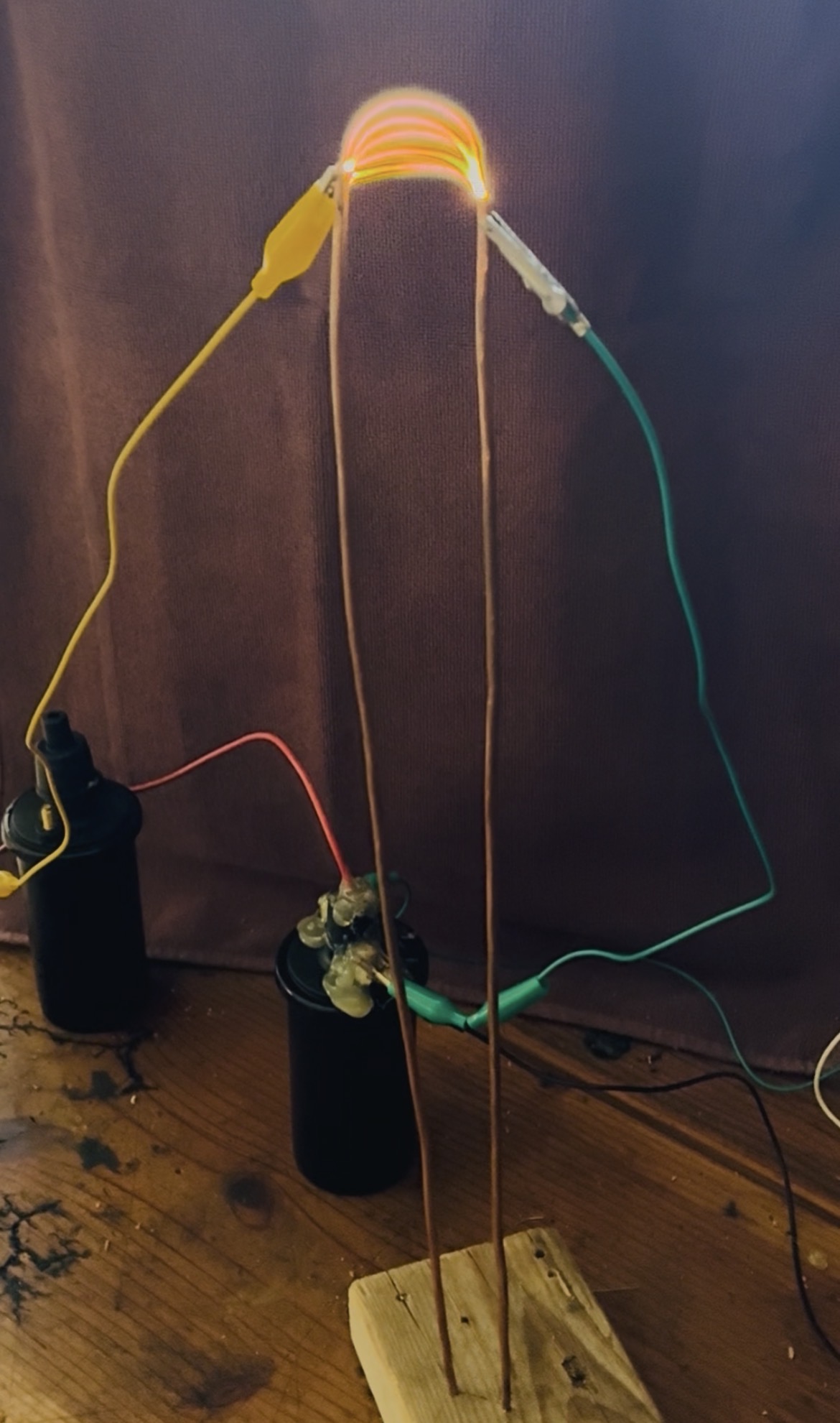
If one looks closely at an image of the arcs created by this process (shown below), it’s apparent that there really are only 5 discrete arcs, and not a continuum of them as would be expected if the TRIAC did not switch off.

Arcing:
For this section, I wanted to go a bit more in-depth on the way arcing works and why the Jacob’s ladder behaves the way it does.