Jacob’s Ladder
A Jacob’s ladder is a high-voltage electrical device that produces a rising arc between a pair of straight, nearly-vertical electrodes. It’s often used in science demos to explain arcing, or in movies when a generic background electrical device is needed. The conditions this device needs to operate are:
- A power supply which provides at least 10kV (in my case it was around 25kV)
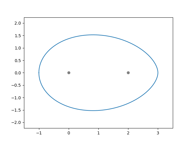
- Two identical, straight electrodes, which are angled ever-so-slightly away from each other such that the distance between them increases with the height from the base.
- Relatively still air around the electrodes.
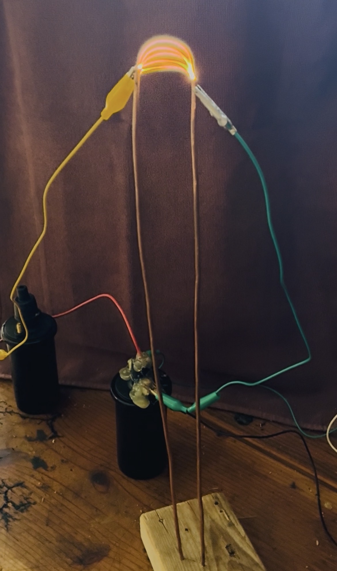
The principle of operation is somewhat surprisingly mainly thermodynamic: as the arc heats the air around it, the heated pocket will rise, and the heated air creates a more favorable environment for the arc to exist in, so the arc rises with it. The process continues until the arc either reaches the end of the electrodes, or they get far enough apart that there is no longer enough current to sustain an arc of that length. A new arc will then form at the bottom, where the electrodes are the closest and arcing is most favorable.
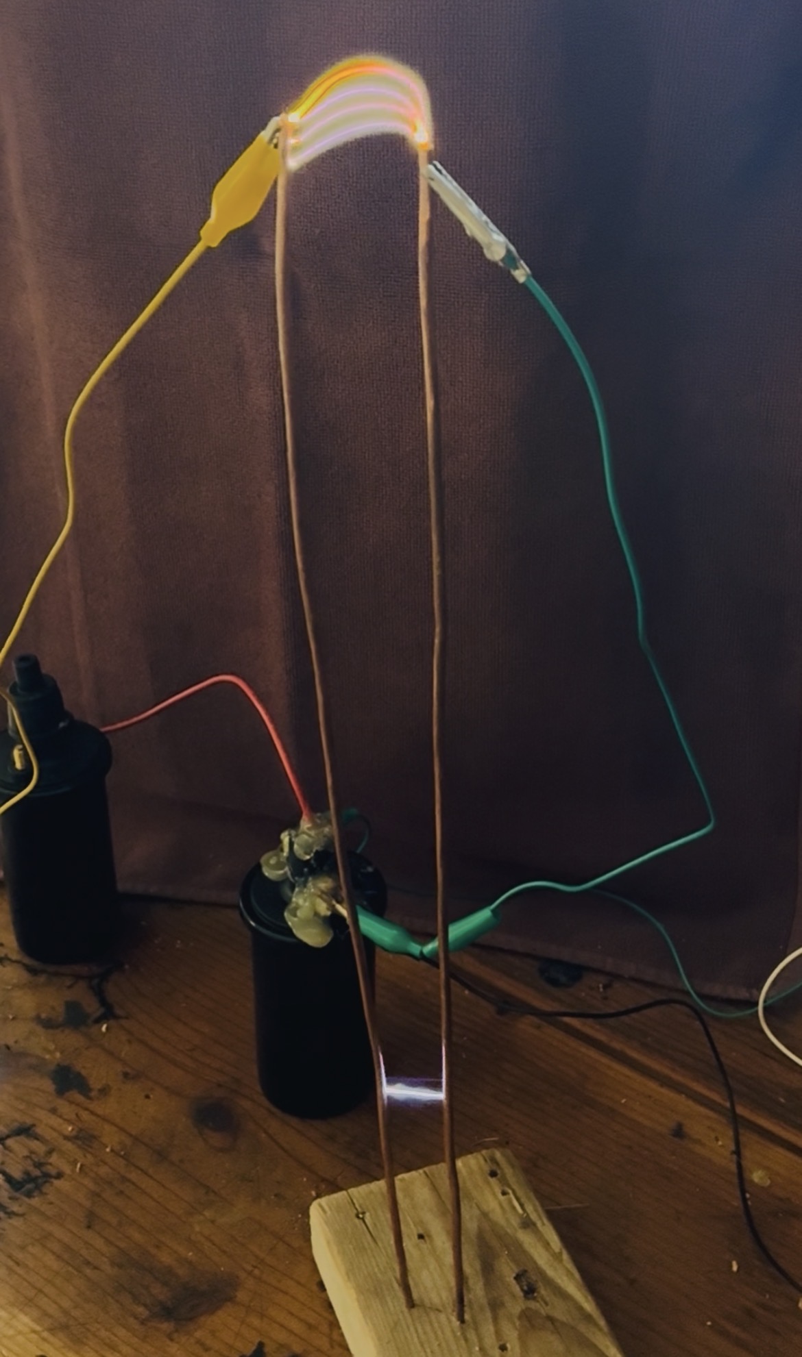
This process is highly volatile, and even slight disturbances in electrode spacing and straightness have large impacts in performance. In effect, this meant trying many different angles and spacing to achieve best results, which got the arcs to around 2-2.5 inches before reseting.
Upon taking a still frame from the above GIF, an interesting effect becomes apparant: there are always 5 arcs in one frame. This is because a standard video camera shoots at 24 frames per second, and there are 120 arcs per second (2 per cycle at 60 Hz). This can be seen clearly in the following:
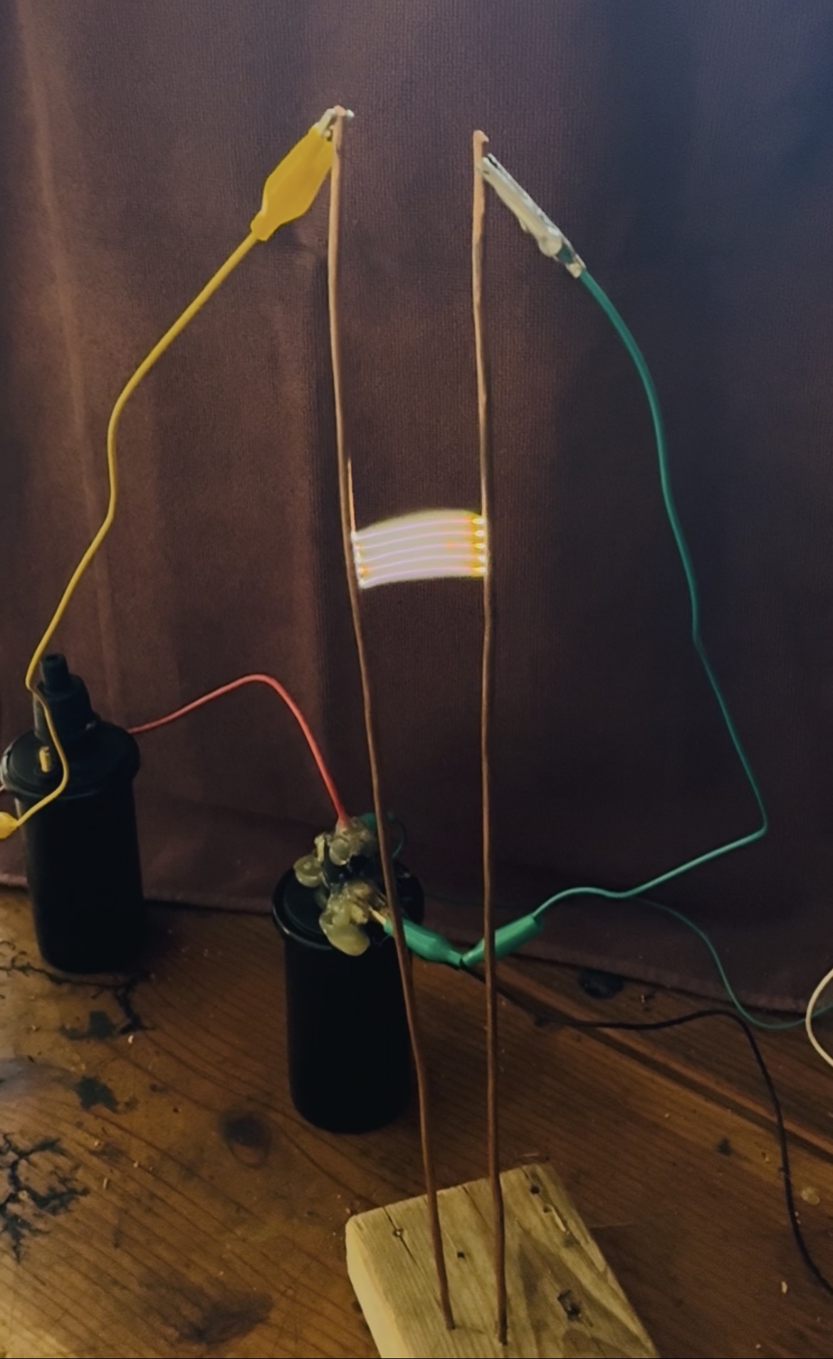
Zooming in on the first image:

there are clearly 5 arcs per frame.
The power supply:
The power supply I built for this project was incredibly simple to assemble in practice, but has intriguing underlying theory. The components required were a car ignition coil, a 250v 20uF capacitor, and a TRIAC dimmer switch (which is the most common type of dimmer switch for lights and other appliances). As seen below, the circuit this represents looks quite complex; however, everything except the transformer (which is the ignition coil) and the 20 uF capacitor is part of the dimmer switch and comes prepackaged.

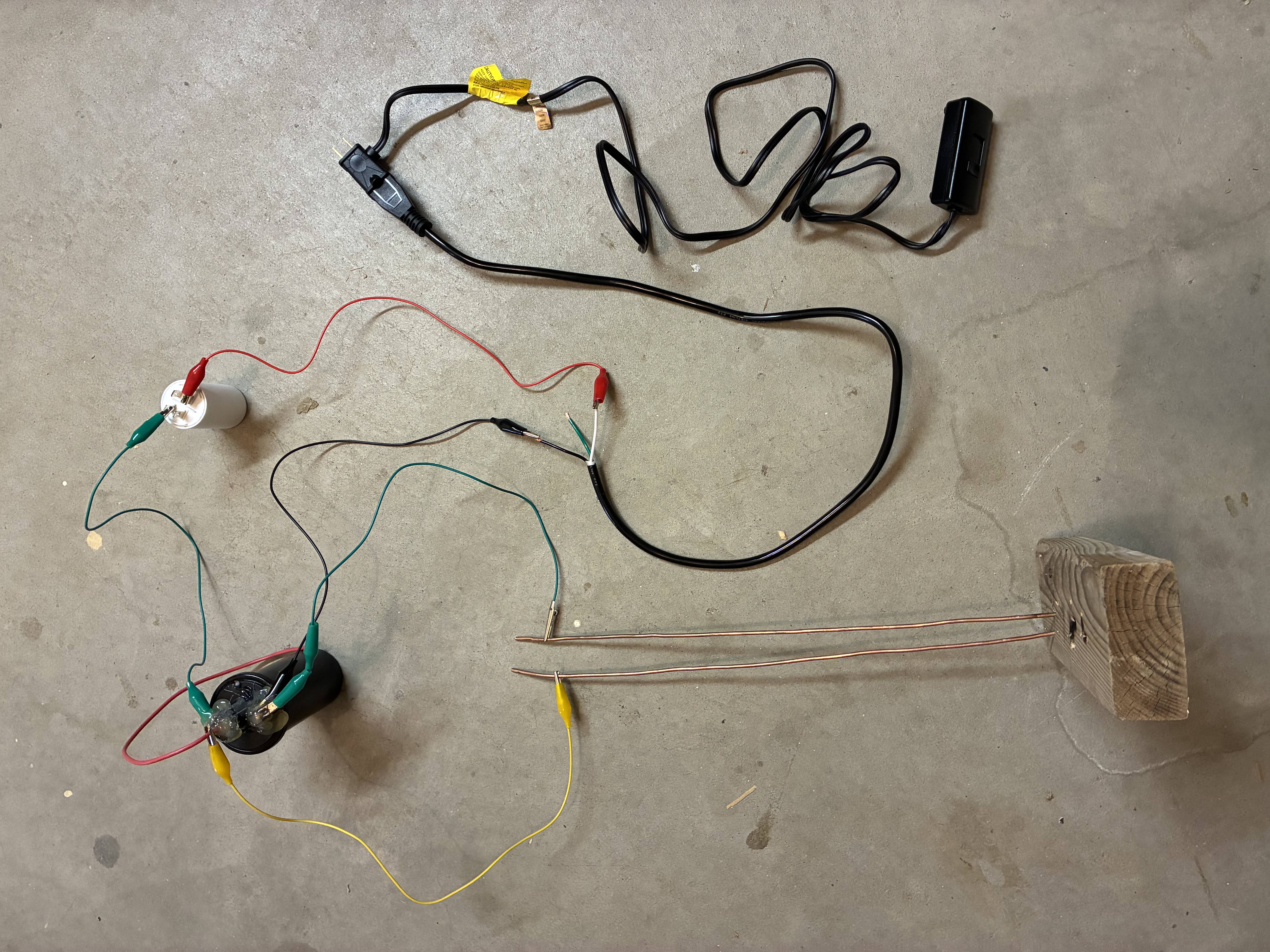
A couple things to note in the image of the actual circuit: first, the TRIAC appears not to be in series with the rest of the circuit. However, because it’s designed to dim lights, it plugs into the wall before the main plug and effectively inserts itself in the circuit on the hot wire in the plug. The second is the hot glue smothering the top of the ignition coil. I put that on as electrical insulation, as the voltages being produced are higher than what the ignition coil was intended for, so it was arcing between the contacts. Finally, there’s a white wire connected to the capacitor that appears to go nowhere. This is what I used to discharge the capacitor when I touched the circuit, as it could have been charged to potentially dangerous voltages otherwise. Unfortunately, on one occasion the spark from discharging the capacitor was so intense it welded the wire to the other electrode of the capacitor, shorting it out. I didn’t notice this, and when I turned the circuit on, the increased current ended up destroying my TRIAC switch.
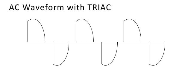
In terms of how this power supply works, it’s once again not the intuitive method. Those familiar with electric components will know that when a changing current (like the AC that’s delivered from outlets) is passed through the primary coil transformer, a voltage is induced in the secondary coil proportional to the rate of change and number of windings in the secondary. However, just the AC waveform by itself along with the igntion coil could only produce around 230 volts - nowhere near the 25kV actually seen. The reason for this is the way the TRIAC works. The way it dims things is by abruptly turning on current once the voltage across it reaches a certain adjustable threshold (this waveform is shown below). This shutoff happens in the span of just a few microseconds, and that collapse creates a massive voltage spike in the secondary coil. When I crunched the numbers to determine how big that spike should be, I found that it was around 100kV, which is of course also not what I observed. I think this is because of both inefficiencies in the power transfer in the inductor, and also parasitic inductance in the high-voltage wiring which impeded the high-frequency spike. Regardless, it’s still more than enough for a good-sized Jacob’s ladder.
Safety:
This is, I think, the most dangerous project I have completed to date. There is exposed wall outlet power, which can be lethal, and touching the arc itself could also be lethal depending on where on your body it is. So, here are the steps I took to ensure my own safety:
- As I mentioned previously, I always discharged the capacitor before interacting with the circuit.
- When I turned it off, I used both the TRIAC and physically unplugging it to do so.
- I stayed over a foot and a half away from the arc while it was live, which was more than enough for the approxiamtely 2 inches it could have jumped to me.
- I never ran it for more than 30 seconds at a time, which is important for fire safety.
- I always wore thick, rubber soled shoes when working with it to insulate myself from the ground as much as possible.
- I always had at least one other person in the room with me when operating it in case everything else failed and I did get shocked.
I researched all of this extensively before doing anything with actual electricty, and alwasy made safety a priority. I’m glad I did, because clearly it’s easy to make mistakes with electricity, as I did when I shorted the capacitor. Another time I turned the TRIAC on too high and it put too much power through the ignition coil (which is only rated for 12v) and burned that out as well. I set up this entire project with the clear intent that a mistake like that could not harm me.